
Product Overview
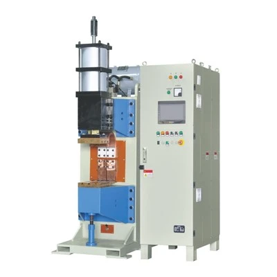
The AC Resistance Butt Welding Machine is an industrial metal-joining system engineered for continuous end-to-end welding of wires, rods, bars, and structural profiles. By passing low-voltage, high-amperage alternating current through abutting workpiece interfaces, the machine generates localized resistive heating to bring metal ends to a forgeable state before applying axial upsetting force. Built for wire drawing lines, hardware fabrication, and component manufacturing, this equipment creates high-integrity solid-state joints across low-carbon steel, alloy steel, stainless steel, and select non-ferrous metals without filler materials.
Working Principle
The welding cycle operates through synchronized electrical heating and mechanical forging:
Workpiece Loading & Clamping: Two metal components are positioned within stationary and movable copper alloy electrode jaws, maintaining precise end-to-end axial alignment.
Interface Abutting & Resistance Heating: The workpieces are brought into initial contact under controlled holding pressure. The AC welding transformer energizes, delivering high secondary current through the interface. Contact resistance instantly converts electrical energy into localized heat, bringing the joint zone to plastic deformation temperature.
Axial Upsetting & Solid-State Fusion: Upon reaching the forging temperature, the upsetting mechanism exerts high axial force. This action expels surface oxides and molten impurities from the interface, consolidating the parent metals into a continuous, high-strength weld joint.
Current De-energization & Jaw Release: The current shuts off as forging completes, allowing the weld zone to cool briefly under clamping pressure before the electrode jaws release the finished assembly.
Key Features
Heavy-Duty Cast Iron Machine Frame: Structural frame absorbs mechanical deflection during high-force upsetting, maintaining linear joint alignment.
Multi-Tap Transformer Voltage Adjustment: Multi-stage secondary voltage taps permit current calibration to match varying workpiece cross-sections and material thermal conductivities.
Water-Cooled Copper Alloy Jaw Blocks: Internal cooling channels serve the transformer windings, secondary busbars, and clamping jaws to maintain thermal stability during continuous operation.
Adjustable Mechanical Upsetting Mechanism: Spring-loaded, pneumatic, or toggle-driven force controls permit precise setting of forge pressure and burn-off distance.
Pneumatic or Lever Quick-Clamping: High-force clamping arms prevent workpiece slippage during the axial upset stage, maintaining low electrical contact resistance.
Applications
Continuous Wire & Rod Drawing: Joining steel, copper, or aluminum wire ends prior to multi-pass wire drawing operations to eliminate re-threading downtime.
Automotive & Railway Hardware: Fabrication of continuous control rods, stabilizer bar stock, ring blanks, and structural wire assemblies.
Hardware & Fastener Manufacturing: Joining circular rings, bucket handles, appliance frames, and threaded rod blanks.
Band Saw & Strip Joining: End-to-end butt welding of carbon steel and bi-metal strip stock for endless saw blade production.
Technical Specifications
|
Parameter |
Standard Value Range |
Customization / Option Scope |
|
Rated Input Power |
35 KVA – 150 KVA |
Up to 300 KVA [Pending Engineering Confirmation] |
|
Input Voltage |
AC 380V / 415V / 480V (50/60 Hz) |
Tailored to site industrial supply |
|
Secondary No-Load Voltage |
2.5 V – 12.0 V |
Multi-tap stepped selection |
|
Max. Welding Area (Low-Carbon Steel) |
Up to 150 mm² |
Up to 400 mm² (Frame-dependent) |
|
Max. Welding Area (Copper Alloy) |
Up to 80 mm² |
Up to 200 mm² |
|
Maximum Clamping Force |
5 kN – 25 kN |
Pneumatic or hydraulic upgrades |
|
Maximum Upsetting Force |
4 kN – 20 kN |
Adjustable spring / pneumatic cylinder |
|
Clamping Stroke Range |
20 mm – 80 mm |
Extended stroke for long profiles |
|
Cooling Water Flow Rate |
$\ge 6\text{ L/min}$ |
Closed-loop chiller system option |
|
Control System |
Synchronous Digital AC Controller |
PLC with HMI interface [Optional] |
Customization Options
Electrode Jaw Contours: Copper jaws machined to match round bars, flat strips, square tubing, or complex profile geometry.
Actuation Systems: Pneumatic cylinders or hydraulic power units replacing manual leverage for high-volume automated lines.
Post-Weld Deburring Attachments: Integrated shear blades or flash trimming units to remove upset beads immediately after welding.
Automation Interfacing: Signal handshake integration with upstream wire pay-off stands, coilers, or downstream processing equipment.
Control Upgrades: Microprocessor-based current controllers featuring weld parameter memory, current monitoring, and line fault diagnostics.
Sample Testing & Quality Validation
Application Review: Evaluation of customer part drawings, material specifications, required tensile targets, and cross-sectional areas.
Parameter Calibration: Lab testing on customer-supplied raw material samples to establish optimal current duration, clamping force, and upset travel.
Mechanical Testing: Destructive tensile testing, 180-degree bend testing, and metallographic cross-sectioning to verify solid-state bond integrity.
Validation Package: Delivery of test reports, weld parameter documentation, macro-section images, and sample video footage prior to machine acceptance.
FAQ
Q: What material preparation is required before butt welding?
A: Workpiece ends must be sheared square and free of heavy rust, oil, paint, or thick scale. Clean metal contact surfaces ensure uniform current distribution across the interface and prevent arcing.
Q: How does material electrical conductivity affect machine sizing?
A: High-conductivity materials like copper and aluminum require higher KVA ratings and current density per square millimeter than low-carbon steel due to rapid heat dissipation away from the joint interface.
Q: What is the difference between resistance butt welding and flash butt welding?
A: Resistance butt welding keeps the end faces in continuous contact under pressure throughout the heating phase, making it ideal for compact solid cross-sections. Flash butt welding uses controlled arcing to flash off surface irregularities before forging, suitable for larger or irregular profile sections.
Q: How are electrode jaws maintained to ensure joint consistency?
A: Electrode jaws require periodic cleaning to remove metal scale and re-dressing to correct surface profile wear. Using chromium zirconium copper jaws extends re-dressing intervals during production runs.
Q: What technical data is required to request a formal quotation?
A: Please provide the target material grade, workpiece cross-sectional dimensions (diameter, width, or thickness), required hourly production rate, and available plant power supply (voltage and frequency).
Hot Tags: ac resistance butt welding machine, China ac resistance butt welding machine manufacturers, suppliers, factory, Car Spot Welding Machine, hand held resistance welder, kel arc stitch welder, smart spot welder, spot welder for auto body, spot welding machine for stainless steel